
The Layout -
The layout of any motherboard is important. Even simple mistakes in component placement or the signal traces can cause major issued in performance and stability. With the ATX form factor we find that this is even truer; the devices we drop onto them demand more and cleaner power while the signal speeds push faster and faster. The Gigabyte G1.Assassin2 is a pretty cool looking board. I like the choice of black with green slots and the military themed look. However, the thing that caught my eye the most was the memory slots. For some reason Gigabyte has chosen to only have four on the board. Considering this is a quad-channel product you are loading up your slots with a single kit. There is no room to add more RAM. If you want to increase the amount of RAM you have you will need to replace what you are already using. This is a little disappointing in a board that is intended to be an enthusiast/ gamer’s product.
 |
 |
While I was puzzling over the limited RAM slots I noticed something else. The 8-Pin ATX Aux power connector has been moved. Instead of its usual place between the CPU socket and the I/O ports it is now near the front edge of the board. Unfortunately it is still in an awkward position and difficult to connect when mounted inside a case (get an extension cable here guys). You might also have noticed that the front two slots of RAM are very close to the front edge of the board. This is an odd design choice as there is plenty of space between the CPU/RAM and the I/O ports. We are not entirely sure what Gigabyte was thinking here, but we hope there is some logic behind it.
 |
 |
One reason that Gigabyte might have had is the way they have broken out the power regulation. You can see this evident in the way the components are spaced out. Just in looking at this area of the board we see several digital power control units and along with their accompanying regulators and chokes. Of course the CPU still gets its very own power regulation and a long line of chokes and caps. I do not think a motherboard would be complete without this.
 |
 |
Moving down the board we come to the area reserved for the CreativeLabs X-Fi. If you look closely you can make out the JRC 4556A and the 3 ST C4558 Op AMPs. We imagine the JRC is what controls the front outputs while the 3 ST C4558’s take care of the rest. The Creative CA20K2-2AG Audio Processor and its 128M of Hynix memory stand out quite clearly along the back edge of the board.
 |
 |
Taking a look at the peripheral slots we find three PCIe x16 mechanical slots. However, only PCIe 1 and 3 are x16 electrical. Slot 2 is only x8. This configuration should still lend to some good gaming performance with the right cards. We also can clearly see the Killer E2100 chip and its 1GB of Samsung DDR2. 
Moving on from the interesting items like the Killer E2100 NPU and the Built in Creative X-Fi we come to the more mundane headers for things like USB, TPM (Trusted Platform Module), front panel audio and the panel controls; nothing exciting really. For SATA ports you get a total of eight. Two are controlled by a Marvell SATA 3.0 controller (the grey ones that are set aside) these are part of the G-SATA that Gigabyte likes to put on their boards. The rest are come from the X79 chipset and break down into four SATA 2.0 (the black ports) and two SATA 3.0 (the white ones).
 |
 |
In keeping with the military theme Gigabyte has put a heatsink that is shaped like a pistol over the X79 chipset. This is a cool looking item, I just hope that it is able to actually perform its job and does not end up as a large heater inside of a case. 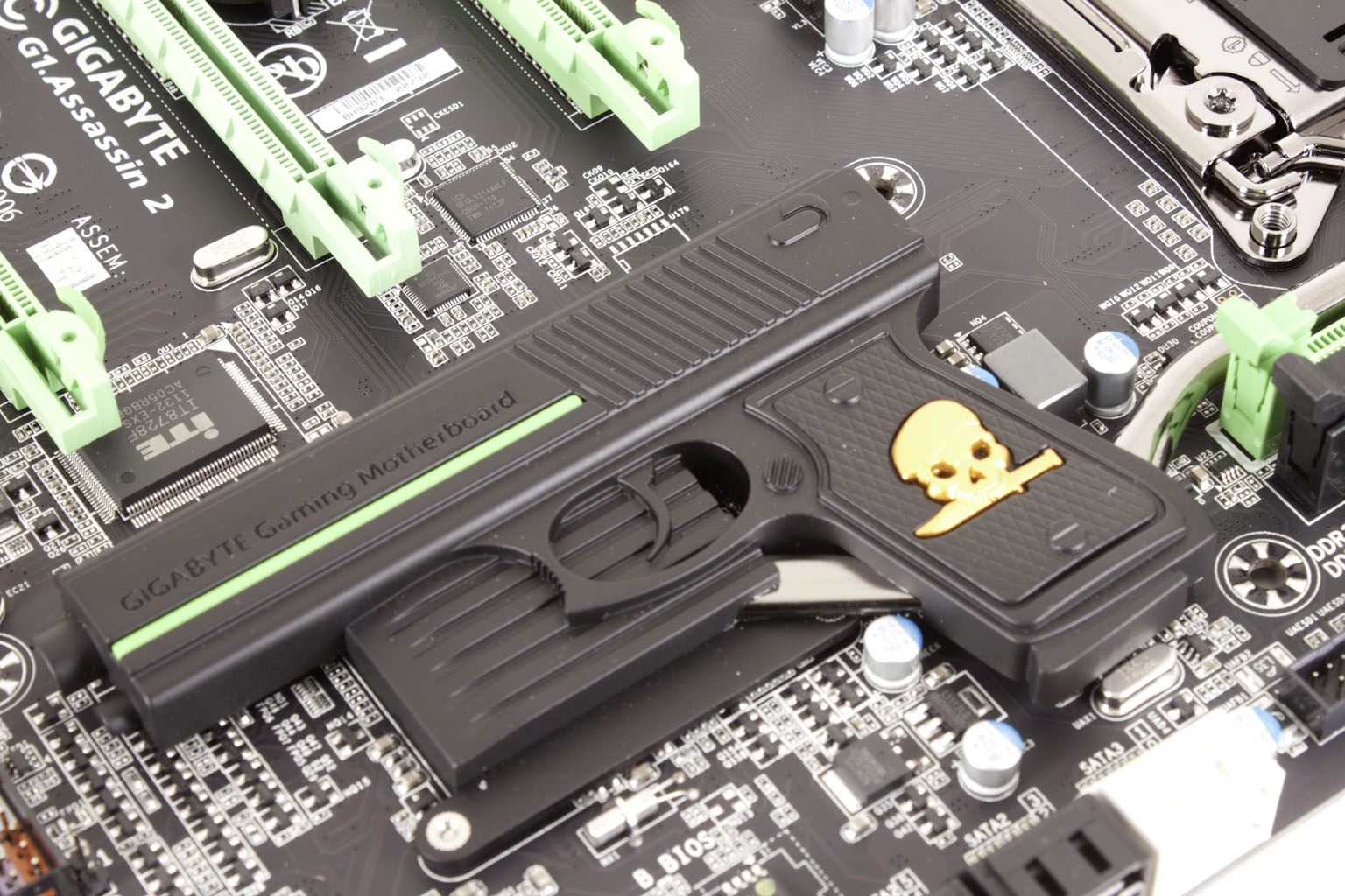
The I/O ports on the G1.Assassin2 are not bad, but again I think I was expecting more. There are only two USB 3.0 ports this time and while there are plenty of eSATA and powered USB 2.0 ports I was still hoping for more. Gigabyte did include an overclocking button that allows you to quickly and easily overclock your system. Simply press the button to OC and press it again to return to defaults. The button right under this allows you to switch between the two BIOSes on the G1.Assassin2. This is great if you want to configure each BIOS for a different performance style. You can configure BIOS 1 to have much faster memory and BIOS 2 to push the CPU.
 |
 |
All in all I like the design, but I am still thinking that the lack of memory slots is going to come back and haunt us. Still that is for later; instead let’s move on to talk about the features of the G1.Assassin2.