The Layout -
The layout of any motherboard is important. Even simple mistakes in component placement or the signal traces can cause major issued in performance and stability. With the ATX form factor we find that this is even truer; the devices we drop onto them demand more and cleaner power while the signal speeds push faster and faster. Another review, another ATX board with the same basic layout and design flaws. However these are not specific to any one manufacturer and while they are annoying, so far, they do not impact performance.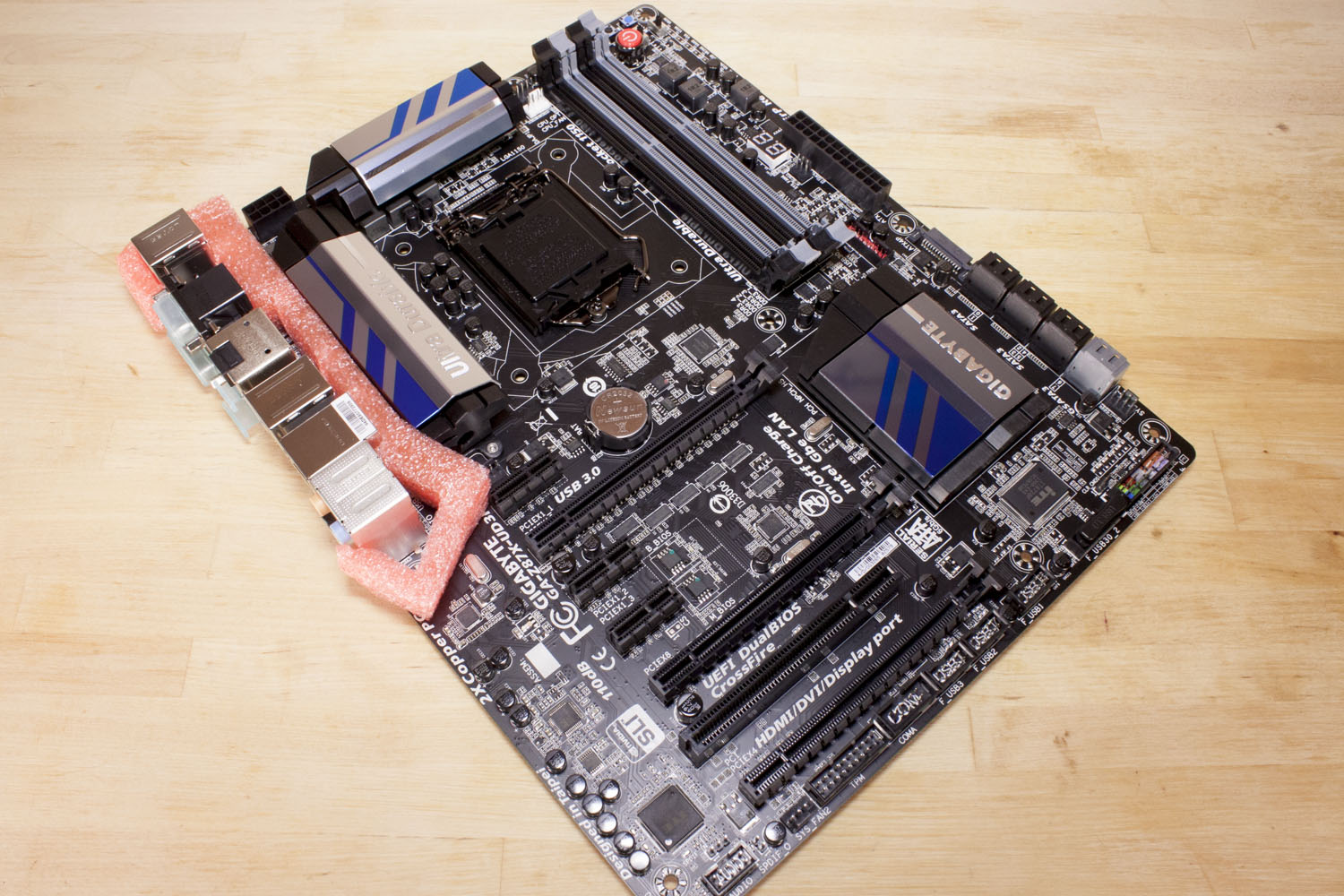
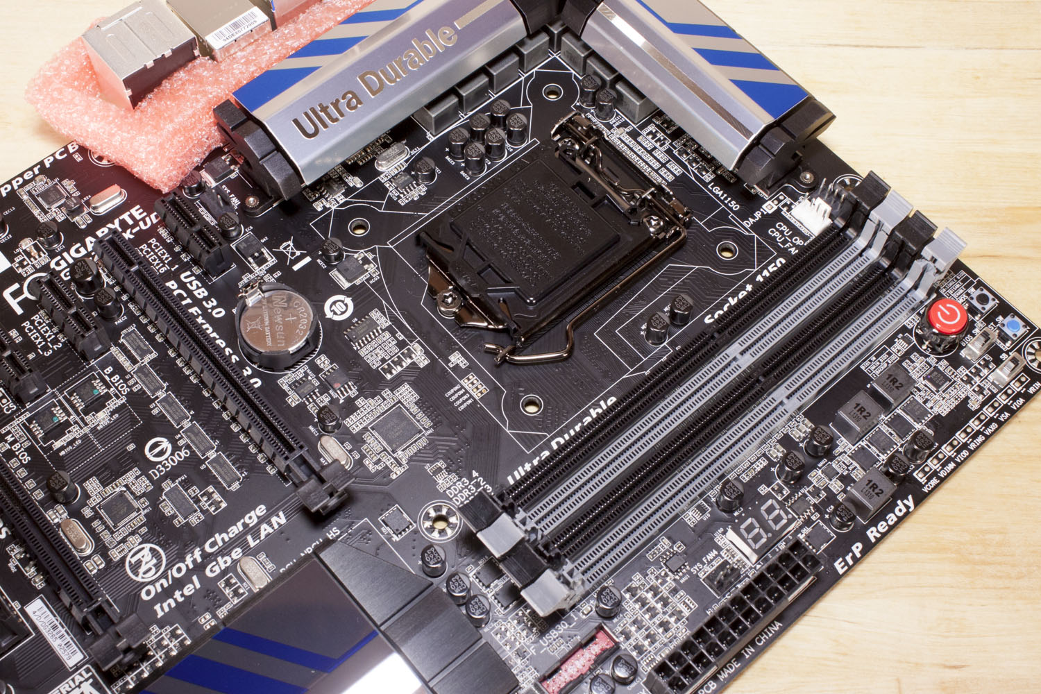
So let’s start our walk around in the typical place. Looking at the upper half of the board we see a very familiar layout with a few minor exceptions. You get the 24-oin ATX power socket, a USB 3.0 header, four RAM slots and some power hardware for the memory. Gigabyte has added in a few things in this area, in addition to the normal items you also get a dual LED diagnostic display and a cluster of controls.
 |
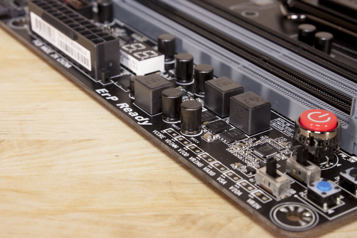 |
For controls you get a large hard mounted power button, a reset button (blue) a clear CMOS button and two switches. The switches are interesting because they allow you to set enable of disable the dual BIOS on the Z87X-UD3H and which BIOS you want to use. This is a hand little feature if you plan on doing a bunch of overclocking, or if you want to test a BIOS before you commit to it. In addition to these switches, Gigabyte is also giving you a string of voltage monitoring points. Again, this is a great addition to the board if you plan on using it for overclocking.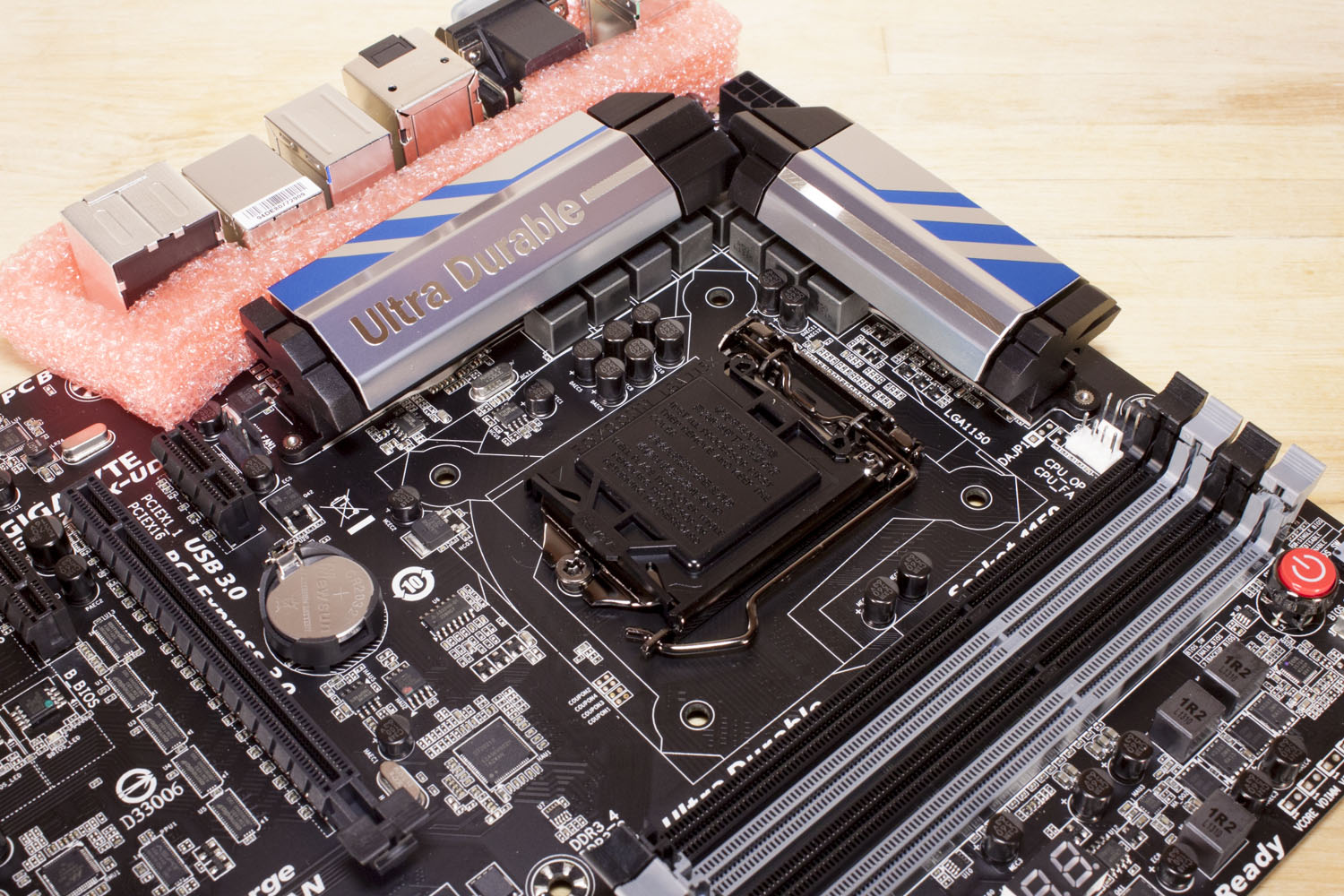
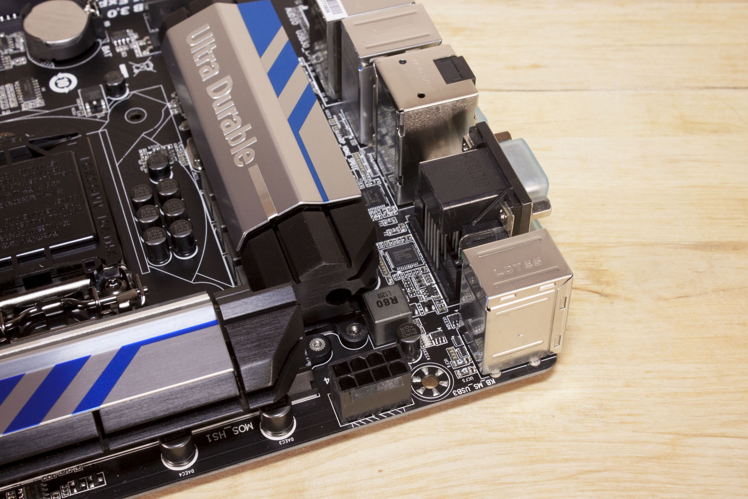
Looking around the CPU socket (LGA 1150) we find a pair of 4-pin fan headers that are intended for use by the CPU cooler you chose. We also find our favorite pet peeve. That is the 8-pin Aux power connector. This is a common annoyance with modern ATX boards and not anything specific with Gigabyte so let’s keep moving.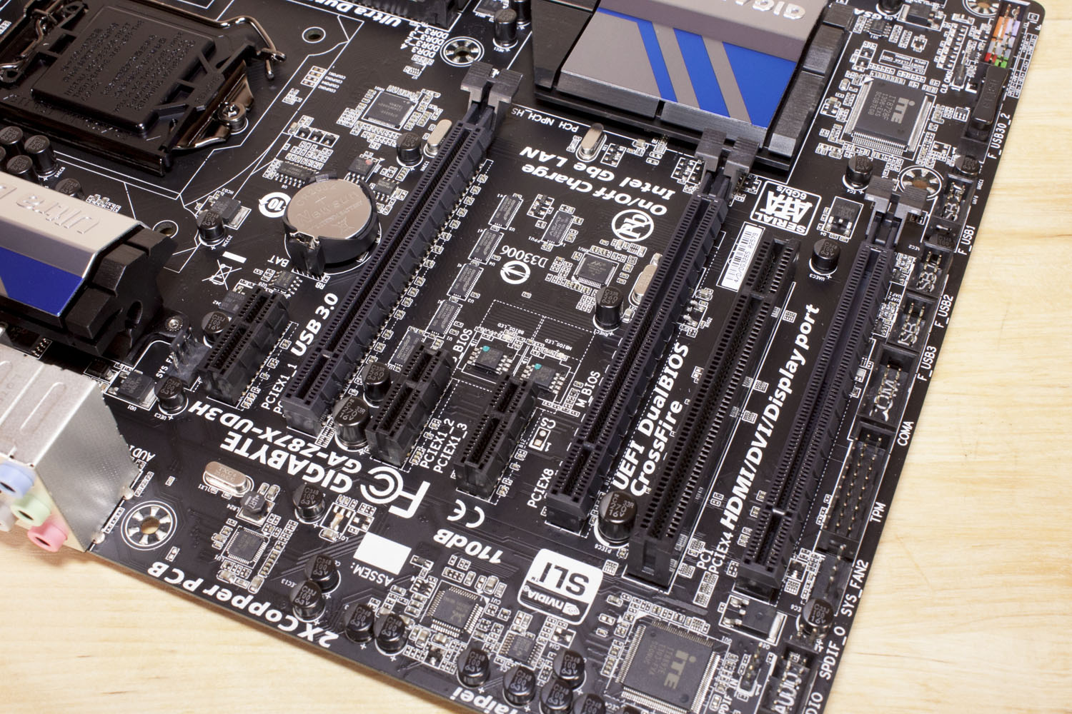
Our next leap is to the lower half of the board where we find three x16 mechanical slots, 3 x1 slots and a PCI 2.1 slot. Unfortunately there is only one slots that gives you x16 electrical, the others are x8 and x4. This means you will get standard SLI or Crossfire, but nothing more than a pair of cards.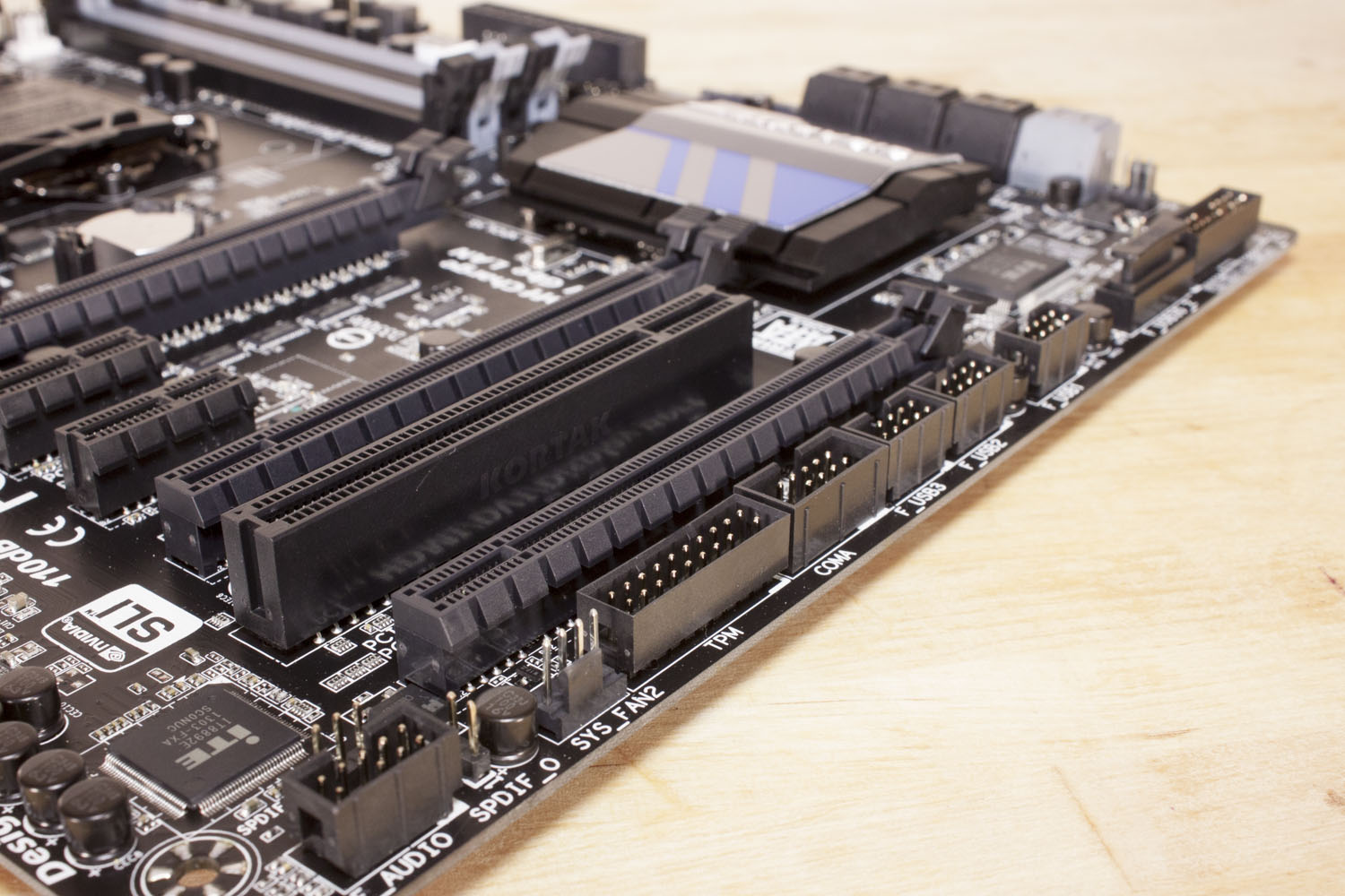
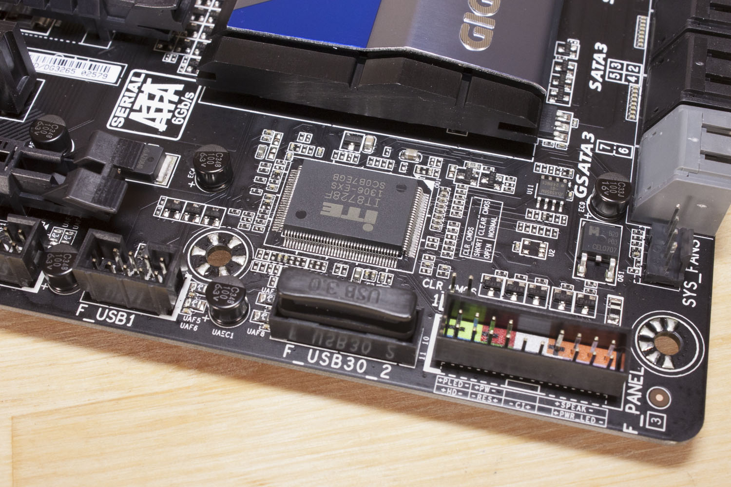
Looking along the lower edge we find the usual suspects, audio headers, USB headers, and the front panel pin-out. One nice extra along this line is a second USB 3.0 header that is on the board.
 |
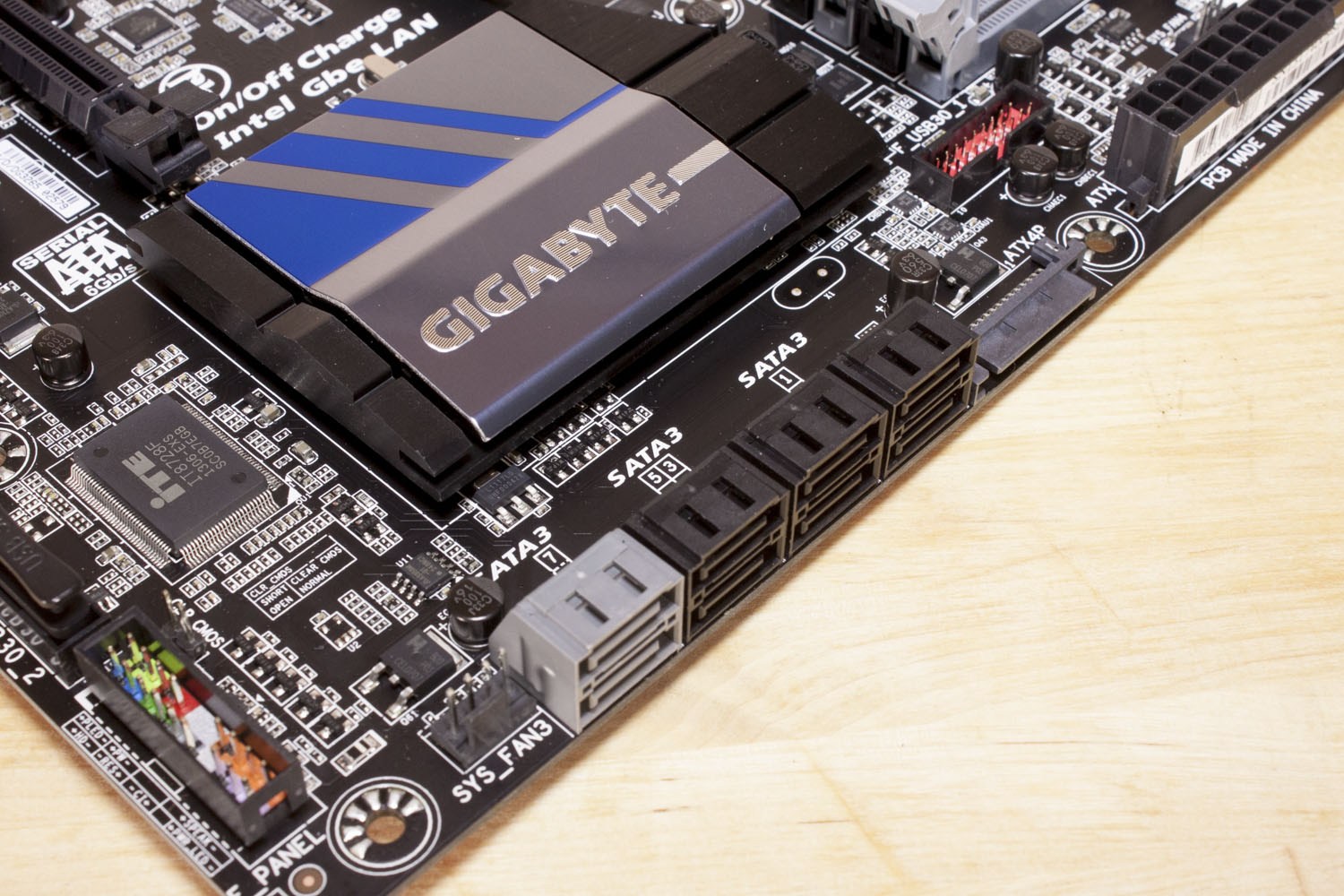 |
For SATA you have a six ports from the SATA Controller on the Z87 chipset and a pair from the Marvell 88SE9172. Speaking of the Z87 chipset, Gigabyte has decided to use a newer design with to protect this crucial part of the motherboard. It looks nice, but we will reserve judgment until later. Lastly in this area we find a SATA power connector that is designed to provide extra power to the board for your overclocking fun.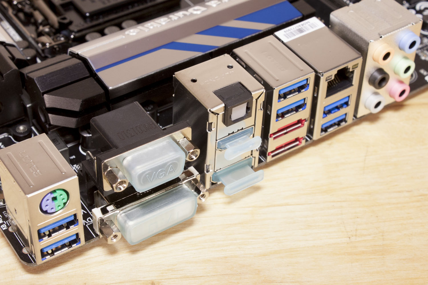
Moving around to the back we find a typical layout. You get a combo PS/2 port, several USB 3.0 ports, multiple video out ports, two eSATA ports, a LAN port and of course 8-channel audio. In all a nice design and layout. You can check out more of our comments in our walk through video.


