The Layout -
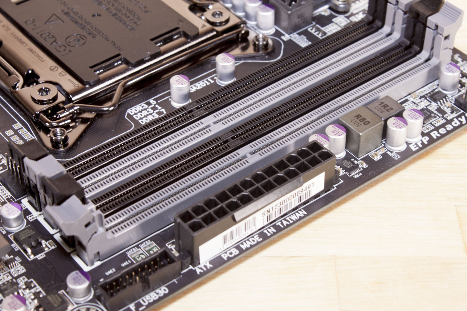
The layout of any motherboard is important. Even simple mistakes in component placement or the signal traces can cause major issued in performance and stability. With the ATX form factor we find that this is even truer; the devices we drop onto them demand more and cleaner power while the signal speeds push faster and faster. The Gigabyte X79-UP4 is an ATX based board which is currently the most common board layout on the market (at least the DIY market). The layout follows the same flow that is has since it was introduced. The only difference from the original design is that with the X79 you get two banks of RAM on either side of the 2011 socket.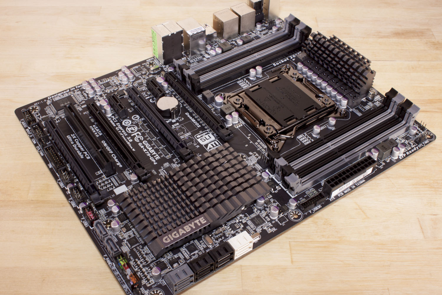
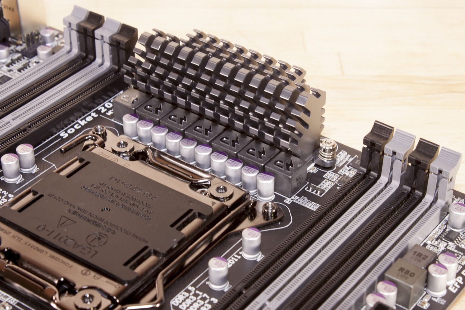
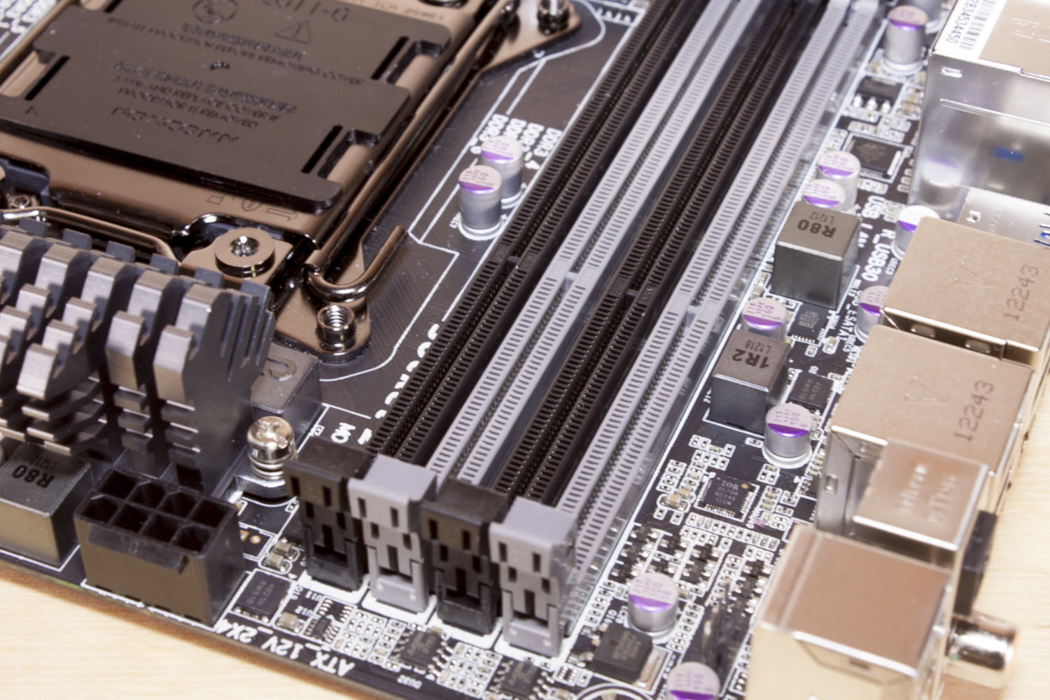
One thing that the dual RAM banks does is make the CPU power design and layout a little more complicated. On the X79-UP4 Gigabyte went with a more compact design than on some of their other boards. This is not a bad thing, but unless it is very efficient we might see some issues during overclocking. The height of the heat sink might also create some issues when plugging in the 8-pin aux power. This is one of the common problems on almost all ATX motherboards, so the placement here is not just a Gigabyte problem.
 |
 |
 |
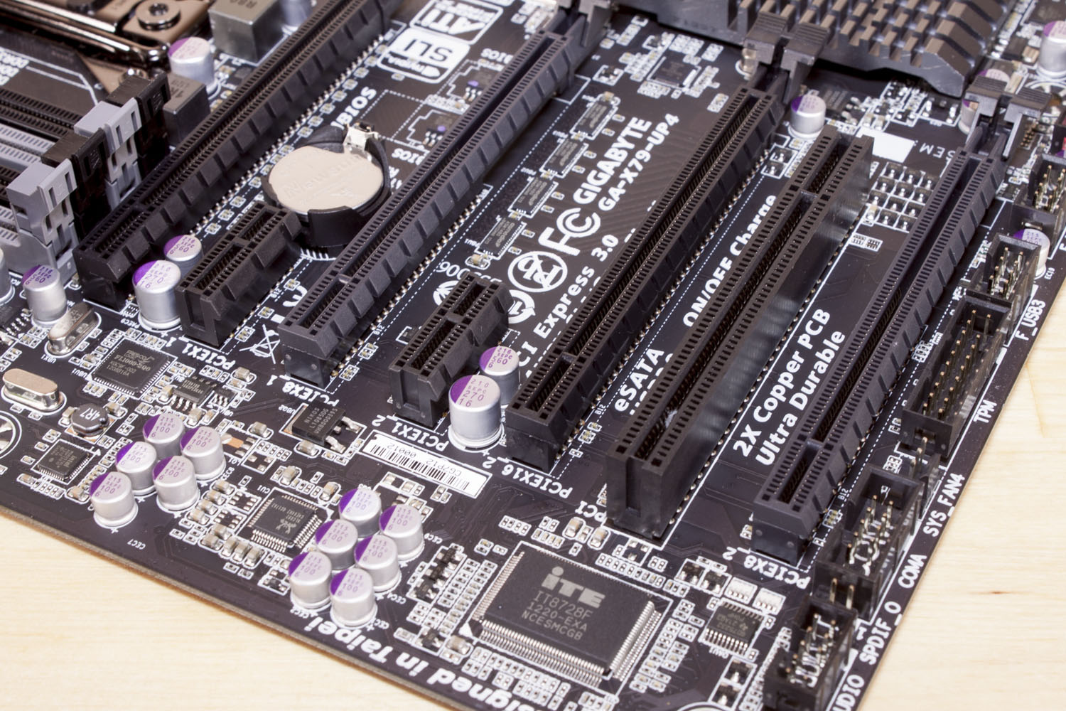
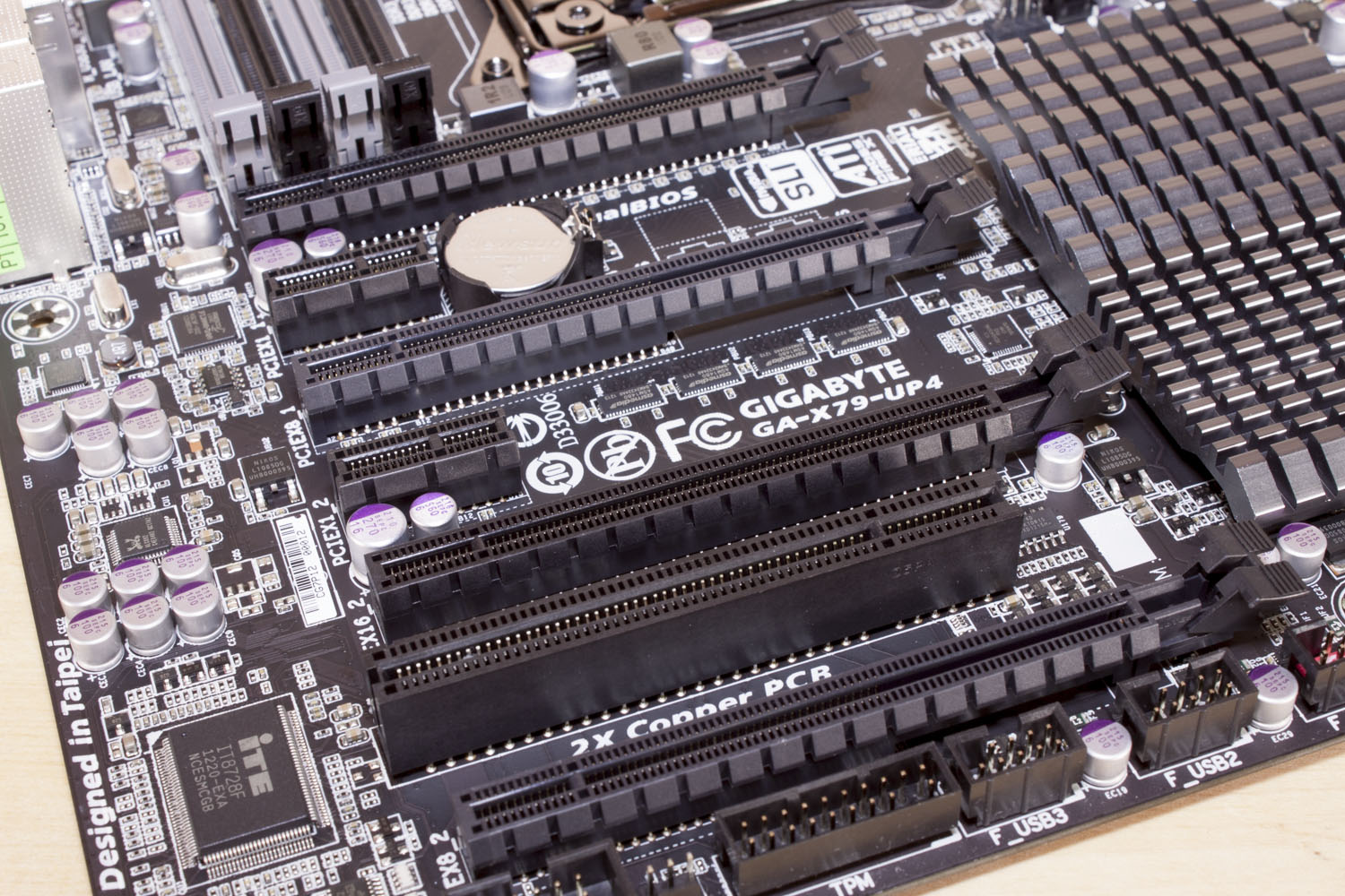
Moving down to the lower half of the board we find four PCIe x16 mechanical slots along with two x1 slots and an old fashioned PCI slot. In reality you are only getting two full x16 slots (slots one and three). The other two are x8 electrical. Using these will bring one of the x16 slots down to x8 as well. That means if you want full x16 SLI use slots one and three. If you want three-way or quad then you are going to get brought down to x8. Still it is pretty obvious that the X79-UP4 is designed with gamers, benchmarkers, or graphics professionals in mind.
 |
 |
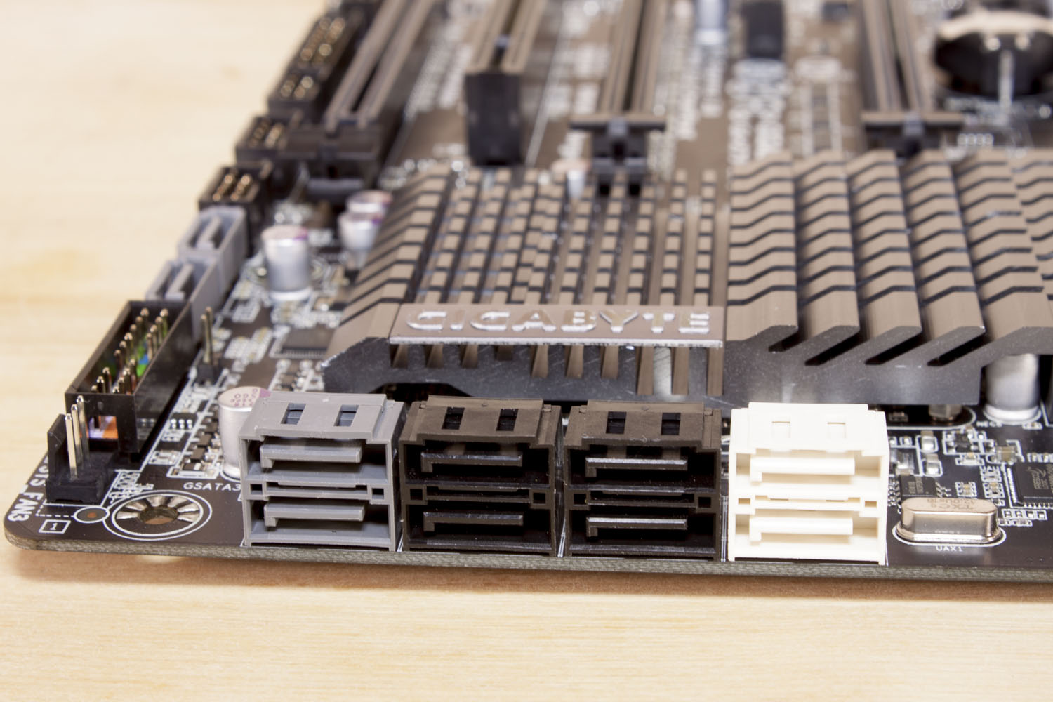 |
Moving to the other end of the board we find the MCP under an interesting looking heatsink and a nice selection of SATA ports. There are four grey ports that are powered by a Marvell 88SE9172 SATA 3.0 controller. The four black ports are SATA 2.0 while the remaining white ports are SATA 3.0 and powered by the Intel X79 chipset.
The layout is pretty clean considering the amount of components that need to be packed into a relatively small space. You can check out our video walk through below.